
 Process
 CAD
CAD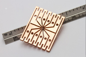 Advantages
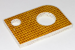 Capabilities
Process of Waterjet Cutting
Waterjet cutting utilizes a high pressure stream of water to cut by erosion a narrow line in stock material. In an industrial setting a mix of abrasive is added to the nozzle to make the process abrasive waterjet cutting, thus allowing for cutting on foams, plastics, rubbers, and steel alloys.
Setting up for waterjet cutting is a skill that requires experience and solid documentation. The vibration from the cutting power can cause materials to shift if they are not set up properly. In addition if material is not flat or stressed to be flat there could be adverse interference with the nozzle during pathing, resulting in down time.
The engine of the Waterjet is a direct-drive pump. Traditionally hydraulic intensifier pumps are less efficient compared to the direct drive pump which allows more net power to the cutting nozzle, resulting in a faster cut.
In operation the waterjet will undercut corners and swing wide on curves when moved as one would move a traditional rigid cutting tool. To dial in precision OMAX eliminates potential cutting issues by accurately predicting the motion and shape of the cutting stream by using their PC based motion control system. The final product is a fast and accurate part.
CAD
MET enjoys working with our customer’s engineering department to confirm and improve design of the products we manufacture and supply. OMAX Waterjet units use OMAX proprietary software named Intelli-MAX. Within the software there are different applications, but the production translation software is called MAKE. This software requires MET engineering to import a customer CAD file and prepare it to be cut from the Intelli-MAX software.
Omax waterjet supports a wide range of compatible CAD file types that work with the Intelli-max software. Listed below are the compatible and preferred types of files to submit to MET for quote and production:
- DXF
- DWG
- AI
- ORD
- SVG
- STEP
Submitting CAD Files
When submitting CAD files for waterjet fabrication, the considerations below make for an easy transition for MET engineering:
- Draw part to scale
When drawing your part in Intelli-MAX LAYOUT or other CAD program, use a scale of 1:1. If not scaled 1:1 please identify the scale. It’s easy to resize the part file if necessary keeping the correct relative dimensions if you start with a 1:1 scale. - Double check provided CAD drawings to make sure they are clean and complete
Lines on top of lines, disconnected lines and an excessive number of endpoints in your drawing can prevent or slow down the process of turning the drawing into a tool path. - Confirm drawing dimensions match from CAD or PDF
If you draw a circle that is 5.3″ (13.4 cm) diameter, but then put a dimension on it that says it is 5.0″ (12.7 cm) diameter, it will still be cut at 5.3″ (13.4 cm) diameter. Therefore, draw it the size you want it, so it gets cut that way.
Advantages
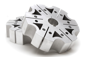
Produces no Hazardous Waste The waterjet cutting process offers flexibility that is not seen in other cutting processes due to the ability to cut irregular shapes from almost any material with exceptional precision and edge quality.
The immediate advantages of Waterjet Cutting include:
- Accuracy of cutting tolerances +/- .003” typical and up to +/- .001”
- Edge quality can be controlled by 5 different cut quality options
- Superior edge quality to other types of 2D laser/CNC cutting offerings
- Limitless cutting thickness profile – .005” thin metals up to 6” thick granite
- Wide variety of substrates that can be processed
- No Heat Affected Zone (HAZ) to keep materials true to their composition
- No material distortion
- Quick change over layouts for prototyping
- Efficient and cost effective for thicker materials
- Produces no hazardous waste
Capabilities
Material Cutting Thickness varies by material type, but commonly the thickness cutting spectrum ranges from .005” thick up to 6” in thickness with a caveat that edge quality at certain higher thicknesses is harder to control.
Material Cutting Capabilities
- All metals (except for carbides)
- All rubbers, plastics, foams, epoxy-reinforced composites
- All glass (except for tempered)
For safety of our employees, MET is not set up to and will not cut materials that contain lead, cadmium, mercury, or beryllium.
Machine Cutting Envelopes & Table Sizes
- OMAX 5555
- 4’7” x 4’7” Cutting area
- 6’8” x 5’5”Table Loading Size
- OMAX 55100
- 8’4” x 4’7” Cutting Area
- 10’6” x 5’5” Table Loading Size
Common Materials
- Aluminum
- Copper
- Brass
- Inconel
- Titanium
- Hastelloy
- Tool Steel
- CRS/HRPO Steel
- Stainless Steel
- Cast Acrylic/Plexiglass
- Plastic
- Rubber
- Composite
- Granite